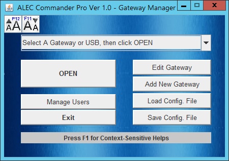
| If you are running the Alec Commander Pro you will first be asked to
select the Gateway Configuration file which contains the definition of all the gateways
that Alec Commander Pro manages. After the configuration file has been loaded you will be
brought to the Gateway Manager as shown on the left diagram below. If you are
running the Alec Commander Basic, you will not be asked to load a gateway
configuration file but you will be brought straight to the simplified gateway manager as
shown on the right. The different background color of the two versions is meant to let you
quickly identify which version of Alec Commander that you are running.
- Note: Since the Alec Commander Basic only allows you to connect to the
Alec ZC001 via the USB port, all gateway related functions are not available. They are
shown as greyed out button mainly to keep the consistent look and feel as the Alec
Commander Pro. The only things you can do on the Basic version is to click the OPEN button
to configure the ZC001 via the USB Virtual Comm Port and quit the Alec Commander Basic
program by clicking on the Exit button.
The Gateway here refers to an Alec IoT Gateway e.g. the model GW-E01 that forms a
communication bridge between the Alec Commander Pro software and the Alec Zone Controllers
ZC001.
The Gateway GW-E01 has an Ethernet port and it can be plugged directly to a local area
network running TCP/IP protocol. It also has an isolated RS485 port which it can connect
using simple, low cost twisted pair cable in parallels to all the Alec ZC001. When the
Alec Commander Pro needs to contact a particular zone controller it will send via Ethernet
a command to the Gateway IP Address. The Gateway that receives the command packet will
convert the command string into RS485 serial data and send it out of its RS485 port.
When the Alec Commander Pro sends the command it will embed the device ID (01 to FF hex
- FF is reserved for the Gateway) into its command packet. When the Gateway receives the
command packet it will check the ID and if the packet is not destined for the Gateway
itself (ID=FF) it will be sent out of the RS485 bus. All the ZC001 are listening on the
RS485 bus and the ZC001 whose ID matches the command string is obliged to send a response
string within 150ms. When the Gateway receives the response string it will then
format it into a TCP packet and return the response packet to the Alec Commander Pro.
It is therefore very important that every ZC001 that is connected to the Gateway be
assigned a unique ID (from 01 to FE hex, FF is reserved for the Gateway). When a ZC001 is
first shipped from the factory it will assume the default ID = FF which is the same as the
Gateway ID. If its ID is not subsequently set to between 01 and FE then it is
non-contactable by the Alec Commander via the Gateway, but it will also not disrupt the
communication of other ZC001 that have properly-assigned ID.
The Alec Commander Pro software can manage up to 100 Gateways, and each Gateway can
connect up to 128 zone controllers ZC001. So whether you have a small installation with a
single Gateway and a few ZC001s, or a large buildings with multiple Gateways and thousands
of zone controllers they all can be managed easily by a single instance of Alec
Commander!
If that is not sufficient, you can run multiple instances of Alec Commander Pro
software, with each instance loading a different configuration file where each file can
contain up to 100 Gateways. Imagine an entire city bloc of lightings could be
managed by the Alec Commander Pro software!
Each ZC001 has a built-in Micro USB port and thus allowing it to be programmed and
configured with or without connecting to the RS485 bus. It is the only way to configure
and program a ZC001 if it is installed as a standalone unit without RS485 connection to a
Gateway.
If you have a ZC001 with you for the first time you will need to get a Micro USB cable
in order to connect to it using Alec Commander software. A Micro USB port is the exact
same port that is used on billions of Android smart phone and countless other electronic
gadgets and therefore a micro-USB is very readily available from practically any phone or
electronic outlet or online store.
- Note: When the ZC001 is not connected to the AC power such
as when you first take it out of its packaging box, it can draw 5V power from the PC's USB
port to power its low voltage portion of the circuitry, thereby allowing you to configure
it offline on your desk without wiring it to the main power!
When you first install the Alec Commander software you will be required to install the
USB Driver. If you have correctly installed the driver your computer will recognize it as
a Virtual COM Port and Alec Commander will be able to connect to the ZC001 via its USB
port.
To configure a new ZC001, click on the drop down menu "Select A Gateway or USB,
then click OPEN" and select the "USB Virtual Com Port" (if you are running
the Alec Commander Basic this is the only option available and is selected automatically).
The following USB Device Manager screen will open:

In the above example the "TRiPLC USB" is recognized by Alec Commander only if
the PC's USB is already connected to ZC001 micro USB port. In this example it has been
assigned COM port 6 by the operating system, but your PC may assign it a different COM
port number. (The COM port number could be re-assigned using the PC's Control Panel
-> Device Manager-> Ports (COM & LPT)).
If you have not connected the micro USB cable to the ZC001 then connect to it now and
Alec Commander will recognize the connection and display it on the Gateway Address
Bar as shown in the above diagram.
The layout graphic on the right pane for USB port illustrates how the USB cable is to
be connectedto the USB port on the Alec ZC001. The left pane device table is not editable
for USB connection. What you need to do now is to click on the  button to for Alec Commander to connect to the ZC001 via its USB port. button to for Alec Commander to connect to the ZC001 via its USB port.
Once connected, Alec Commander will query the ZC001 for its ID and will append that ID
onto the Device Table. This will be the only device that will be added to the table and
you can now configure, program or control the ZC001 by following the procedure described
in the Device Manager.
When you select a Gateway from the drop down menu and click the "OPEN"
button, Alec Commander Pro will open up the Device Manager
for that particular gateway. On the Device Manager the
ZC001 that have been installed will be displayed graphically on a layout background
picture that represents the actual layout of your premises, making it extremely intuitive
to configure, control and program any ZC001 that are connected to the Gateway.
For a quick demo, select the "Default Gateway" and then click the "Edit
Gateway" button.
 
To setup the gateway, the most important parameters are the IP Address, the Username
and Password (if enabled) and these have to be entered in their corresponding text boxes.
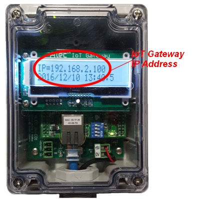
A new Alec IoT Gateway is default to "Obtain IP Address Automatically", which
means that the Gateway would obtain an IP address automatically assigned by the DHCP
server on your LAN. The IP address is displayed on first line of the Gateway's LCD display
for ease of setup, as shown below:
 |
- Note: An automatically-obtained IP address could change
after some time by your LAN's DHCP server and it may become inaccessible if you are not
aware that it has been changed. If you want to use the IP address assigned by the router,
we recommend that you go to your router's setup page (please refer to your router's
reference manual) to reserve a specific IP address for the Alec IoT Gateway so that in
future the Gateway will always be accessible using the same IP address.
- Alternatively you can also assign a static IP address to the Alec IoT Gateway, but you
will need to also define the Subnet Mask and the Router IP address. This is described
later in the "Connect & Config" Gateway section of this help file. However,
you must first be able to connect to the gateway using the known IP address that it
displays on its LCD screen.
|
If you have connected your Alec IoT Gateway to your LAN and have taken note of its IP
address, you should now enter it into the "IP Address" field in the "Edit
Gateway" dialog box shown above. The default TCP port number is 9080 which is what
the Alec IoT Gateway is already configured to use and is non-editable.
After you have made changes to the Gateway parameters, click "Save" to save
the changes to the Gateway configuration file.
You can now click the "Connect & Config" button and Alec Commander will
try to connect to the Gateway using the IP Address that you have entered. If connected
successfully Alec Commander would retrieve the network settings from the Gateway and
allowing you to make any changes.
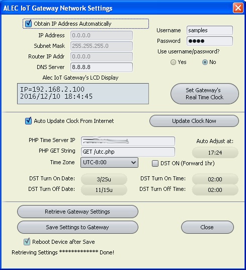 |
If you check the "Obtain IP Address Automatically" then the IP
Address, the Subnet mask and the Router IP Addr fields will become non-editable since
these information will be obtained from the DHCP server when the Gateway request an IP
address from a DHCP server on the LAN. The DNS Server it is currently not used by Alec
IoT Gateway and may be left empty, or you can enter 8.8.8.8 which is a global DNS server
IP Address hosted by Google.
The RTC is very important to a fully functional Alec lighting control solution because
the program scheduler needs to know that date and time in order to properly execute the
programmed settings at different time of the day, day of the week or on a particular day
of the year. Also, in order to log the real time energy consumption of the lighting
fixtures controlled by the ZC001 it needs to use the RTC so that the data are correctly
recorded.
The Alec IoT Gateway has a built-in battery-back, 32.768KHz watch crystal controlled
RTC that is reasonably accurate and is not affected by power failure. In addition, since
the Gateway is connected to the LAN, it is capable of updating its RTC by getting the more
accurate RTC data from a server on the Internet.
Every minute, the Gateway will broadcast its RTC data to all the connected ZC001 to
synchronize all their RTCs so that the programmed action can be carried out accurately.
Therefore in a connected Alec lighting solution you only need to set the RTC on the
Gateway and you don't have to set the clock on individual ZC001, which is very convenient
especially if your location need to handle Daylight Saving Time changes twice a year. |
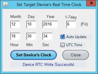
To manually set the Gateway's RTC, you simply click on the "Set Gateways' Real
Time Clock" button and a dialog box will open allowing you to set the Gateway's RTC
to a new value. To makes it simpler the Set RTC dialog box automatically populates and
update the data using the PC's realtime clock data. But you can uncheck the auto-update
check box and manually enter a new RTC value if need be.
Countries or regions that adjust their clock to cater to the shorter day in winter and
longer day in summer have to adjust the clock at specific dates twice a year. Fortunately
only the Gateway RTC need to be adjusted and it will broadcast its new clock data to all
the ZC001 that is connected.
You can manually adjust the DST settings by clicking on the "DST ON (Forward 1
Hr)" check box and then save the settings to the Gateway. When the checkbox is
selected (checked) it means DST is turned ON and the Gateway will forward the clock by 1
hour. When the checkbox is de-selected (unchecked) the Gateway will reverse the clock by
one hour. Note that the clock change will only take place after you have saved the new
settings to the Gateway by clicking the "Save Settings to Gateway" button.
Alec Commander also lets You automate the Daylight Saving Time cross-over by
programming the dates and the times when the Day Light Saving is turned ON as well as when
the Day Light Saving is turned OFF. In the above example, the DST is programmed to be
turned ON on the 2nd Sunday at 2:00am and it is turned OFF on the first Sunday of
November at 2:00am, which is the settings for many states and provinces in North America.
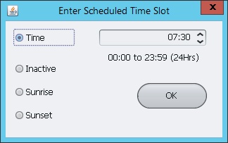
You can change the Date and Time of DST ON and OFF by clicking on their respective
button and a Date-Picker Dialog or Time Picker Dialog will appear to let you define the date and
the time for the change over. If your region does not use DST you can set them as
"Not Used" and "Inactive" so that they will not take effect
automatically.
|
Since the Alec IoT Gateway is connected to the LAN, if it is allowed to open an
outgoing port to connect to the Internet (depending on your company's Internet policy),
then it can connect to a PHP script on a web server to obtain the more accurate Internet
time that the web server is synchronized to periodically.
If you select the "Auto Update Clock From Internet" check box, then once a
day Alec Gateway will try to connects to the webserver IP address specified in the
"PHP Time Server IP" field and it will try to "GET" the PHP file
utc.php. The webserver's PHP engine will execute the PHP script "utc.php" and
return a response string to the Alec Gateway that contains the current UTC date and time
reported by the server. Alec Gateway then uses the RTC data, together with its Time Zone
and whether Daylight Saving Time is ON or OFF to compute the actual time for its RTC.
When an Alec IoT Gateway is shipped from the factory it contains the special IP address
of a TRi web server allowing it to instantly use the TRi server to update its RTC once a
day. Alec Gateway users are permitted to use this IP address for this purpose. The
"Auto Adjust" time is the time when the RTC update take place and is randomly
set at a particular time of the day. This is to prevent too many Alec Gateways from trying
to update their RTC at the same time, which could overload the web server and making some
updates fail. You may however change the update time if the random time does not fit your
purpose.
If in the event that the TRi web server IP address has changed then the RTC auto adjust
will fail and the Gateway will report the error on its LCD screen. If this is the case,
please check with TRi staff to obtain a new IP address for the webserver.
If your company has an IntraNet webserver that is periodically synchronized to the NTP
time server to obtain more accurate time you can specify the IP address of your Intranet
Time server and ask your IT department to add a file "utc.php" to your
webserver. The "utc.php" file is very simple and can be downloaded from: alec.triplc.com/download/php/utc.zip
|
To add a new Gateway to Alec Commander. Click the "Add Gateway" button and a
new dialog will appear as follow:
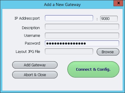 When you have entered all the details, click the
"Add Gateway" button to add it to the Gateway Manager. |
The most important parameters that you must enter are the IP
Address, the Username and the Password fields (if in use at the Gateway). The
Description field has no control significance so you can enter any descriptive text to
describe what the Gateway is - could be by address, functions, department or anything
meaningful.
The "Layout JPG File" text box shown in the Edit Gateway windows allows you
to specify the location of the JPG file that represent the actual layout of the premises
where all the ZC001s that are linked to this Gateway are installed.
The "Default Gateway" uses a "defaultLayout.jpg" file that are
stored in the layout subfolder of the Alec Commander installation folder. You can
change the layout file here by clicking on the "Browse" button to locate a new
JPG file. Alternatively the layout file can also be changed in the Device Manager by right clicking on the layout diagram itself
after the Device Manager has been opened (Click here for details).
Once you have entered the IP Address, the Username and Password you should click the
"Connect & Config" button to try connect to the Gateway to configure its
network settings and its real time clock settings, as described in the "Edit Gateway" section of this help file.
|
|
